The UML Class diagram is used to visually describe the problem domain in terms of types of objects (classes) related to each other in different ways.
There are 3 primary inter-object relationships: Association, Aggregation, and Composition. Using the right relationship line is important for placing implicit restrictions on the visibility and propagation of changes to the related classes, a matter which plays an important role in understanding and reducing system complexity.
Association
The most abstract way to describe static relationship between classes is using the Association link, which simply states that there is some kind of a link or a dependency between two classes or more.

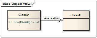
Weak Association
ClassA may be linked to ClassB in order to show that one of its methods includes parameter of ClassB instance, or returns instance of ClassB.
Strong Association
ClassA may also be linked to ClassB in order to show that it holds a reference to ClassB instance.

Aggregation (Shared Association)
In cases where there’s a part-of relationship between ClassA (whole) and ClassB (part), we can be more specific and use the aggregation link instead of the association link, highlighting that the same ClassB instance can also be aggregated by other classes in the application (therefore aggregation is also known as shared association).

It’s important to note that the aggregation link doesn’t state in any way that ClassA owns ClassB nor that there’s a parent-child relationship (when parent deleted all its child’s are being deleted as a result) between the two. Actually, quite the opposite! The aggregation link is usually used to stress the point that ClassA instance is not the exclusive container of ClassB instance, as in fact the same ClassB instance has another container/s.

Aggregation v.s. Association
The association link can replace the aggregation link in every situation, while aggregation cannot replace association in situations where there’s only a ‘weak link’ between the classes, i.e. ClassA has method/s that contain parameter of ClassB, but ClassA doesn’t hold reference to ClassB instance.
Martin Fowler suggest that the aggregation link should not be used at all because it has no added value and it disturb consistency, Quoting Jim Rumbaugh "Think of it as a modeling placebo".
Composition (Not-Shared Association)
We should be more specific and use the composition link in cases where in addition to the part-of relationship between ClassA and ClassB - there’s a strong lifecycle dependency between the two, meaning that when ClassA is deleted then ClassB is also deleted as a result

The composition link shows that a class (container, whole) has exclusive ownership over other class/s (parts), meaning that the container object and its parts constitute a parent-child/s relationship.
Unlike association and aggregation, when using the composition relationship, the composed class cannot appear as a return type or parameter type of the composite class. Thus, changes to the composed class cannot propagate to the rest of the system. Consequently, usage of composition limits complexity growth as the system grows.
Clarification: It is possible for a class to be composed by more than one class. For example, ClassA may be composed by ClassB and ClassC. However, unlike aggregation, instances of ClassB and ClassC will never share the same ClassA instance. That would violate the propagation of changes principle. ClassB instance will have its own instance of ClassA, and ClassC instance will have its own instance of ClassA.
Measuring system complexity
System complexity can be measured simply by looking at a UML class diagram and evaluating the association, aggregation, and composition relationship lines. The way to measure complexity is to determine how many classes can be affected by changing a particular class. If class A exposes class B, then any given class that uses class A can theoretically be affected by changes to class B. The sum of the number of potentially affected classes for every class in the system is the total system complexity.
______________________________________________________________________________
Recommended Book on UML
You should read Martin Fowler’s book: UML Distilled: A Brief Guide to the Standard Object Modeling Language (3rd Edition). It’s pure gold.
______________________________________________________________________________
I am also answering questions on Quora @https://www.quora.com/profile/Aviad-Ezra
My other blog: Interview Questions (and answers) by Aviad Ezra


